HvArm: Chapter 0: Introduction to UEFI and the EFI Development Kit
This is the first part of a series about developing a passthrough hypervisor for ARM (AArch64). Since I followed a few years ago the amazing Hypervisor Development for Security Researchers training by Satoshi Tanda, I wanted to build a similar hypervisor for an ARM platform. In this series, the target platform is QEMU’s virt machine type with EDK2 UEFI firmware — a setup that lets us develop and test without dedicated hardware. By the end of the series, we will have a minimal hypervisor that boots as a UEFI application to transparently virtualize the operating system that loads after it.
This first article lays the groundwork. It begins with virtualization fundamentals on both x86 and ARM, explaining how hardware support differs between the two architectures. It then walks through the UEFI boot process in detail — understanding where our hypervisor fits in the boot flow is essential. Finally, it covers the development environment setup so that by the end you can boot into a UEFI Shell on an emulated AArch64 machine, and execute a simple application.
The main purpose of a passthrough hypervisor is to examine and control an operating system transparently. Because it virtualizes only the existing CPUs and physical memory — no device emulation, no scheduler, no virtual hardware — the code base stays small and auditable. That simplicity makes it an ideal foundation for security research: it can be extended to support single-stepping, memory introspection, fuzzing hooks, or any instrumentation that benefits from sitting below the OS without the OS knowing.
Virtualization on ARM vs Intel/AMD
These two platforms took fundamentally different paths. Intel had to retrofit hardware virtualization onto an architecture that was never designed for it, while ARM had the luxury of designing virtualization support from scratch with the benefit of hindsight. This led to substantial architectural differences.
Virtualization extensions on x86
Intel and AMD worked independently to create a processor extension to support hardware virtualization. In late 2005, Intel released two Pentium 4 CPUs that supported the VT-x extension, and AMD, about six months later, released three Athlon 64 CPUs that supported the AMD-V extension. While similar concepts are shared between the two extensions, they expose different instructions and methods to configure virtual CPUs and second level address translation. Let’s focus on VT-x for the rest of this section.
Intel introduced two new modes:
- VMX root mode: where the Virtual Machine Monitor (VMM) or hypervisor runs. Essentially the traditional Current Privilege Level 0 (CPL0) or Ring 0 with additional control.
- VMX non-root mode: where the guest Operating System runs. It thinks it is Ring 0 but certain operations will produce a VM Exit and trap to the hypervisor so that it can handle them.
Some might call the VMX root mode: “Ring -1” to express the idea of the security boundary like the one between Ring 3 and Ring 0. In reality no new Ring was created.
The Virtual Machine Control Structure (VMCS) is used to describe a virtual CPU. It is an opaque structure that contains:
- Guest-state area: register values, segment descriptors, CR0/CR3/CR4, EFLAGS, etc.
- Host-state area: hypervisor’s register state to restore on VM Exit.
- VM-execution control fields: there are operations and events that can provoke a VM Exit conditionally like accessing Model Specific Registers (MSRs) and these fields are used to configure them. Some other operations or events provoke VM Exit unconditionally like
cpuidand these cannot be configured and must be handled by the hypervisor. - VM Exit Control Fields: this area controls how the processor behaves during the transition out of the guest (VM Exit). For example it is possible to save debug registers.
- VM Entry Control Fields: this area controls how the processor behaves during the transition into the guest (VM-Entry). For example it is possible to inject an event like an interrupt into the guest.
- VM Exit Information Fields: this is a read only area to give information on what caused the current VM Exit so that the hypervisor can know what it has to handle.
Extended Page Table (EPT) is the term Intel decided to use for Second Level Address Translation (SLAT). The guest OS maintains its own page tables to translate Guest Virtual Addresses (GVA) to Guest Physical Addresses (GPA). The hypervisor maintains the virtual machine’s EPT to translate GPA to Physical Addresses (PA). All that is handled in hardware by the Memory Management Unit (MMU).
Lifecycle of the hypervisor:
- Configure the CPU for VMX operations
- Enter VMX operations
- Configure a VMCS per vCPU
- Enter VMX non-root mode
- The guest runs natively until there is a VM Exit
- The hypervisor handles the VM Exit
- Re-enter VMX non-root mode if desired
- and so on
Virtualization on ARM
ARM introduced hardware virtualization support in ARMv7 with the Virtualization Extensions (2010), and then significantly matured it in ARMv8-A (AArch64). Because ARM designed this knowing the lessons from x86, the result is architecturally much cleaner.
ARM AArch64 defines four Exception Levels (EL), which directly encode the virtualization hierarchy into the privilege model:
| Level | Purpose | Equivalent x86 Concept |
|---|---|---|
| EL0 | User space applications | Ring 3 |
| EL1 | (Guest) Kernel space | Ring 0 |
| EL2 | Hypervisor | Ring 0 VMX root mode or Ring -1 |
| EL3 | Secure Monitor | Closest would be SMM |
The key difference from x86 is that the hypervisor occupies an entirely different exception level with its own dedicated set of system registers, its own translation regime, and its own exception vectors. There is no need for an opaque “current VM” structure like the VMCS — the architecture separates hypervisor and guest state by design.
Trapping and configuration
ARM does not have the equivalent of a VMCS structure. Instead, the Hypervisor Configuration Register (HCR_EL2) is the primary control surface. It is a 64-bit register whose individual bits determine which guest operations trap to EL2. For example, setting the TWI bit traps WFI (Wait For Interrupt) instructions, TSC traps SMC calls, TVM traps writes to virtual memory control registers, and AMO/IMO/FMO route asynchronous aborts, IRQs, and FIQs to EL2 respectively. This is conceptually similar to the VMCS execution control bitmaps, but with a key difference: because HCR_EL2 is a single 64-bit register, it cannot provide the same per-MSR or per-I/O-port granularity that Intel’s bitmap-based approach offers. The trapping is coarser — you trap entire categories of operations, not individual instances.
Complementary registers extend the trapping surface. CPTR_EL2 controls trapping of floating-point and SIMD/SVE instructions. MDCR_EL2 controls trapping of debug and performance monitor accesses. HSTR_EL2 traps accesses to specific coprocessor registers. Together, these registers give the hypervisor fine-grained control over what the guest can do natively and what requires hypervisor intervention.
Context switching
Instead of automatically saving and restoring guest state in a hardware structure (as the VMCS does on VM Exit/VM Entry), on ARM the hypervisor manages context switches entirely in software. When an exception traps to EL2, the hypervisor must save the guest’s general-purpose registers (X0–X30, SP_EL1), key system registers (SCTLR_EL1, TTBR0_EL1, TTBR1_EL1, TCR_EL1, MAIR_EL1, VBAR_EL1, SPSR_EL1, ELR_EL1, and others), timer state (CNTVOFF_EL2, CNTV_CTL_EL0, CNTV_CVAL_EL0), and GIC virtual CPU interface state. On re-entry, all of this must be restored. This is more work than the hardware-managed VMCS approach, but it gives the hypervisor complete flexibility: it can modify any register between exit and entry, selectively skip saving state it knows hasn’t changed, or inject state modifications transparently.
Second Level Address Translation
The term for SLAT on ARM is Stage 2 Translation, and it behaves similarly to EPT:
- Stage 1 controlled by the guest kernel in EL1: translates Virtual Addresses (VA) to Intermediate Physical Addresses (IPA)
- Stage 2 controlled by the hypervisor in EL2: translates IPA to Physical Addresses (PA)
Both stages are walked by the MMU in hardware. The hypervisor sets the Stage 2 translation base address in VTTBR_EL2 and enables Stage 2 via HCR_EL2.VM. Stage 2 page table entries also carry access permissions and memory attributes, so the hypervisor can control read/write/execute permissions and cacheability for any guest physical page — just as EPT entries do on Intel.
Interrupt virtualization
ARM provides dedicated hardware support for efficient interrupt virtualization. The architecture defines virtual interrupt lines (vIRQ, vFIQ, vSError) that the hypervisor can assert to the guest via HCR_EL2 bits, without needing to inject events through a software structure. More importantly, the ARM Generic Interrupt Controller (GIC, version 3 and later) includes a virtual CPU interface that allows the guest to interact with virtual interrupts directly in hardware. The hypervisor programs the GIC’s List Registers with pending virtual interrupts, and the guest acknowledges and completes them through the virtual CPU interface without trapping to EL2. This is architecturally cleaner than x86, where virtualizing the APIC often requires intercepting MMIO accesses or using the more complex APICv/AVIC hardware acceleration.
Lifecycle of the hypervisor
- Configure EL2 system registers (
HCR_EL2,SCTLR_EL2,VTTBR_EL2, etc.) - Set up the EL2 exception vector table (
VBAR_EL2) - Build Stage 2 page tables for the guest
- Configure trapping behavior (which operations should trap to EL2)
- Program the GIC for interrupt routing
- Enter the guest via
ERET(exception return to EL1) - The guest runs natively until a configured operation traps to EL2
- The hypervisor handles the exception
- Re-enter the guest via
ERETif desired - and so on
We will dive into more details when we implement the passthrough hypervisor.
Type 1 and Type 2 Hypervisors
This sections covers the differences between the two types of hypervisors, what are their benefits and downsides and what is best suited for a passthrough hypervisor.
Type 1: Bare-Metal Hypervisors
A Type 1 hypervisor runs directly on the hardware with no host operating system beneath it. It is the first software to boot (or among the first, in a UEFI environment) and has direct control over all hardware resources. The hypervisor itself provides scheduling, memory management, and device drivers — or delegates device access to a privileged guest.
Examples: VMware ESXi, Xen, Microsoft Hyper-V
On Intel, the hypervisor initializes and enters VMX root operation. It can then run guests in non-root mode. Because no host OS is present, the hypervisor must provide its own infrastructure: an interrupt descriptor table (IDT) and interrupt handlers, APIC configuration for interrupt routing, a memory manager for EPT and internal allocations, and — if running multiple VMs — a scheduler. Some hypervisors include a minimal set of device drivers for essential hardware (serial console, storage, network), while others delegate almost all device access to a privileged guest. With Hyper-V, Windows becomes a privileged guest (the “root partition”) of its own hypervisor, running in VMX non-root mode but with direct access to hardware through the hypervisor. Similarly, Xen uses Dom0, a privileged Linux guest that provides device drivers and management interfaces on behalf of the hypervisor.
On ARM, Type 1 hypervisors are a natural fit for the exception level model. The hypervisor starts at EL2, configures Stage 2 page tables for each VM, programs the GIC for interrupt routing between VMs, and uses HCR_EL2 to trap sensitive operations. Guest kernels run at EL1, and user-space applications at EL0 — the exception level hierarchy maps directly onto the virtualization hierarchy with no architectural contortion required. Like on x86, some ARM Type 1 hypervisors (Xen on ARM, for example) use a Dom0 guest at EL1 for device access and management, keeping the EL2 hypervisor itself minimal.
There is a notable exception on some ARM platforms. Certain ARM laptops that shipped with Windows — like the Lenovo X13s, Microsoft Surface, or Asus Zenbook A14 (all using Qualcomm Snapdragon SoCs) — have firmware that boots the OS at EL1 rather than EL2. The Qualcomm firmware retains a proprietary stub at EL2, and Windows later contacts this stub via HVC to request that it load Hyper-V into EL2. This means third-party hypervisors cannot claim EL2 on these machines — the firmware never offers it. These platforms are not well suited for hypervisor research because native EL2 access is unavailable.
Type 1 hypervisors provide better isolation from the operating system, which is the basis for the “Ring -1” analogy. The hypervisor controls the hardware and the OS runs as a guest with no direct access to the physical address space or privileged configuration. However, they can be more complex to implement: without a host kernel, the hypervisor must build all its own infrastructure from scratch — memory management, interrupt handling, timer management, and whatever device support it needs.
Type 2: Hosted Hypervisors
A Type 2 hypervisor runs on top of a host operating system. The host OS manages hardware, and the hypervisor leverages host OS services (scheduling, memory allocation, device drivers) to create and manage VMs. This is simpler to deploy but adds a layer of indirection.
Examples: VMware Workstation, VirtualBox, QEMU+KVM
On x86, a Type 2 hypervisor runs as a kernel driver. The host OS kernel remains in VMX root mode at Ring 0 and is unaware of VMX non-root execution happening underneath one of its processes. The complexity here is that the host OS “owns” Ring 0, but the hypervisor kernel module temporarily borrows VMX root to launch guests. Interrupt handling, scheduling preemption, and device access all flow through the host kernel, which adds latency but provides compatibility with the full range of host hardware and drivers.
On ARM, there are two ways of implementing a Type 2 hypervisor, and the distinction reflects an important architectural evolution.
The legacy approach (pre-ARMv8.1) required splitting the hypervisor across two exception levels. The host Linux kernel ran at EL1, and a small hypervisor stub was installed at EL2. When KVM needed to perform a hypervisor operation — such as configuring Stage 2 page tables, modifying HCR_EL2, or entering a guest — the kernel driver issued an HVC (Hypervisor Call) to trap into the EL2 stub, which performed the privileged operation and returned. Every hypervisor action required this world switch between EL1 and EL2, adding overhead and complexity. The EL2 stub had to be carefully written, and the split-level design made the code harder to maintain.
ARMv8.1-A introduced the Virtualization Host Extensions (VHE), which fundamentally changed this model. VHE allows the host kernel to run directly at EL2 by enabling two key bits in HCR_EL2: the E2H bit, which redirects EL1 system register accesses to their EL2 counterparts (so the kernel’s reads and writes to SCTLR_EL1, TTBR0_EL1, etc. transparently operate on the EL2 equivalents), and the TGE bit (Trap General Exceptions), which routes EL0 exceptions to EL2 instead of EL1. The net effect is that the kernel runs at EL2 with full access to hypervisor registers, but the code itself doesn’t need to be aware of the difference — register redirection makes it transparent. Guests then run at EL1/EL0 naturally, and guest entry/exit is a straightforward exception level transition rather than a call through a stub. This is how modern KVM on ARM works: the kernel is the hypervisor, and the EL2 stub is gone.
Type 2 hypervisors can be easier to implement because, as a kernel driver, all facilities like memory management, scheduling, and device drivers are readily available. However, they cannot provide the same isolation as a Type 1 hypervisor — the hypervisor shares its privilege level with the rest of the kernel and can be tampered with by code running at the same level.
Passthrough Hypervisor
A passthrough hypervisor is a minimal hypervisor that virtualizes only the existing physical CPUs and memory. No new virtual CPUs are created, no devices are emulated, and no scheduler is needed — there is exactly one guest, and it gets the entire machine. All physical devices are identity-mapped into the guest’s address space, so device accesses pass through to real hardware without interception. While this is quite limiting compared to a full hypervisor, it is precisely that simplicity that makes it valuable.
How it works
The core mechanism is an identity-mapped SLAT configuration. On ARM, the hypervisor builds Stage 2 page tables where every Intermediate Physical Address maps to the same Physical Address (IPA == PA). On x86, the equivalent is an EPT where every Guest Physical Address maps to the same Physical Address (GPA == PA). Because the translation is an identity map, the guest accesses physical memory and MMIO regions at their real addresses with no translation overhead beyond the page table walk itself. From the guest’s perspective, there is no visible difference from running on bare metal.
What the hypervisor does intercept is configurable. By setting specific trap bits (HCR_EL2 on ARM, VMCS execution controls on x86), the hypervisor can choose to trap certain operations — for example, specific system register writes, SMC/HVC calls, or debug exceptions — while letting everything else execute natively. This is where the research value lies: the hypervisor is transparent to the guest under normal execution, but it can observe and intercept specific events of interest. It can log every write to a particular system register, single-step the guest, intercept page table modifications for memory introspection, or hook specific hypercalls for fuzzing infrastructure.
Boot flow
Because a passthrough hypervisor only has one guest and doesn’t need device emulation, a Type 1 approach is best suited. The hypervisor boots as a UEFI application during the TSL phase, before the operating system loads. The high-level boot flow on ARM looks like this:
- The UEFI firmware boots normally through SEC, PEI, DXE, and BDS.
- BDS loads our hypervisor as a UEFI application from the ESP. At this point, execution is in the TSL phase with full boot services available, and the CPU is at EL2 (on QEMU’s
virtmachine, the firmware starts at EL2 and can hand off at that level). - The hypervisor configures EL2: it sets up its own exception vector table, builds identity-mapped Stage 2 page tables covering all of physical memory and MMIO, and configures
HCR_EL2to enable Stage 2 translation and trap the operations it cares about. - The hypervisor deprivileges the UEFI environment to EL1 by setting up the EL1 register state and executing
ERET. From this point on, the UEFI boot services and everything that follows (including the OS boot loader and the OS itself) run as a guest at EL1. - The OS boots normally, completely unaware that a hypervisor is present beneath it.
This approach requires no scheduler, no device emulation, and no interrupt virtualization complexity (interrupts can be configured to pass through directly to EL1). The entire hypervisor can be a few thousand lines of code, which makes it auditable and easy to extend for specific research goals.
What comes next
Future chapters in this series will cover the implementation step by step: configuring EL2 system registers, building Stage 2 page tables, handling traps, deprivileging the boot environment, and extending the hypervisor to be able to boot a Linux operating system.
The Seven Phases of UEFI Boot
The Unified Extensible Firmware Interface (UEFI) replaced the legacy BIOS with a modern, modular firmware architecture defined by the PI (Platform Initialization) specification. Unlike the monolithic BIOS, UEFI breaks the boot process into seven distinct phases, each with a clear responsibility and well-defined handoff to the next.
This section walks through every phase — SEC, PEI, DXE, BDS, TSL, RT, and AL — explaining what each does, why it exists, and how it fits into the overall boot flow.
1. SEC — Security Phase
Purpose: Establish a root of trust, initialize just enough hardware to find and validate the next phase, and handle the platform’s earliest execution entry point.
The SEC phase is the very first platform-specific firmware code that executes after the CPU comes out of reset. On x86, the processor begins execution at the reset vector near the top of the 32-bit address space, which is mapped to the firmware flash device. On ARM platforms, the story is different: the CPU begins at an architecture-defined exception vector, and on many ARM SoCs, execution actually starts in a boot ROM burned into the chip itself. This boot ROM performs initial hardware validation and may load the first firmware stage from flash, eMMC, or even USB before jumping to it — meaning the SEC-equivalent code on ARM often runs after an additional vendor-specific boot ROM stage that has no x86 counterpart.
SEC operates under severe constraints. At this point, no DRAM is available — the memory controller hasn’t been initialized. On x86, the SEC code typically runs directly from flash (execute-in-place, or XIP) and uses the processor’s cache configured as RAM (CAR, sometimes called “no-eviction mode” on Intel platforms) as a temporary stack and data store. This is accomplished by loading the cache with a fixed range of addresses without any backing DRAM, essentially repurposing the L1/L2 cache as SRAM. ARM platforms generally don’t use a cache-as-RAM trick. Instead, most ARM SoCs include a small block of on-chip SRAM (typically 64–256 KB) that is available immediately at reset. This SRAM serves the same purpose — providing a stack and scratch space before DRAM is online — but it’s a dedicated hardware resource rather than a repurposed cache.
SEC’s responsibilities include:
- Handling the reset vector and transitioning the processor into a state suitable for C code execution. On x86, this means moving from the initial real mode to a flat protected or long mode environment. On ARM, the processor typically starts in a privileged exception level (EL3 on ARMv8-A), and SEC configures the exception level hierarchy and may initialize the Generic Interrupt Controller (GIC) at a basic level.
- Initializing temporary RAM — via the cache-as-RAM technique on x86, or using on-chip SRAM on ARM — so that a stack exists for the PEI phase.
- Establishing a root of trust. On Intel platforms, this involves Boot Guard, which uses an Authenticated Code Module verified by hardware against keys fused into the chipset. On AMD, Platform Secure Boot performs a similar function via the Platform Security Processor (PSP), an embedded ARM core that runs its own firmware before the main CPU is released from reset. On ARM, TrustZone provides the hardware isolation, and the trust chain typically starts in the boot ROM or a Trusted Firmware-A (TF-A) BL1 stage that verifies subsequent images. Some ARM SoCs also integrate a dedicated secure enclave similar to AMD’s PSP.
- Locating the PEI core in the firmware volume and passing control to it along with a handoff data block that communicates the location and size of temporary RAM.
SEC is typically written in a mix of assembly (for the very early reset vector code) and C (once temporary RAM is available). It is small and platform-specific. On ARM platforms with a TF-A boot flow, the SEC equivalent often corresponds to the BL1 and BL2 stages of Trusted Firmware, which handle trust establishment and DRAM initialization before handing off to a UEFI firmware payload.
2. PEI — Pre-EFI Initialization
Purpose: Initialize permanent memory (DRAM) and discover the minimum set of hardware required for the DXE phase to execute.
PEI is the first phase that operates with a structured, modular architecture. It consists of the PEI core (also called the PEI Foundation) and a set of PEI modules loaded from firmware volumes. The core provides a minimal dispatch mechanism and service table; the modules are the actual initialization drivers.
PEI begins executing with only temporary RAM — the cache-as-RAM region on x86 or the on-chip SRAM on ARM. Its most critical job is memory initialization — configuring the memory controller and training DRAM. This is an enormously complex task on modern platforms: DDR4/DDR5 training involves signal integrity calibration, timing parameter discovery, and often takes hundreds of milliseconds.
The memory training process differs significantly across architectures. On Intel platforms, DRAM initialization is encapsulated in the Memory Reference Code (MRC), delivered as a binary firmware module within Intel’s Firmware Support Package (FSP). AMD has a comparable binary blob called the AGESA (AMD Generic Encapsulated Software Architecture) code, which handles memory and CPU initialization. On ARM, memory controller configuration is typically provided by the SoC vendor as part of a platform-specific firmware package — for example, as part of TF-A’s BL2 stage or as a vendor-supplied binary. Because ARM SoCs integrate far more varied memory controller designs than the relatively standardized x86 platforms, the memory training code tends to be more diverse and vendor-specific.
After DRAM is available, PEI migrates its data from temporary RAM to permanent memory. On x86, this is known as the CAR teardown — the cache is returned to its normal caching role, and all PEI state transitions to DRAM. On ARM, this migration is simpler since on-chip SRAM remains accessible (it doesn’t need to be repurposed back like a cache), but the firmware still relocates its working state into DRAM for the much larger address space it provides.
PEI also introduces a key architectural pattern: the PEIM-to-PEIM Interface (PPI). These are named interfaces, identified by GUIDs, that PEI modules install and consume to communicate with each other. For example, there are standard interfaces that signal when permanent memory is available, that provide read access to UEFI variables for early configuration, and that offer basic CPU I/O services. This interface mechanism allows PEI modules to be loosely coupled and loaded in dependency order.
PEI also handles sleep state resume. On x86 platforms, when the system wakes from S3 sleep (suspend-to-RAM), PEI must reinitialize the memory controller in a manner compatible with the saved memory context. Crucially, it must then execute the S3 Boot Script to replay necessary register writes and restore hardware state before passing execution directly to the OS waking vector, rather than proceeding through DXE and BDS. This resume path is a major source of complexity and firmware bugs. ARM platforms handle low-power state resume differently: the ARM Power State Coordination Interface (PSCI) standard defines how cores are powered on and off, and the Trusted Firmware typically manages the resume path. Rather than replaying PEI, ARM platforms often retain the memory controller state across suspend (since many ARM SoCs support self-refresh retention without full retraining), and the TF-A firmware restores the CPU context and jumps directly to the OS resume entry point.
PEI culminates by building a set of handoff data blocks that describe the system state — including the memory map, discovered hardware, and locations of firmware volumes — and passes them to the DXE phase.
3. DXE — Driver Execution Environment
Purpose: Initialize the full platform hardware and construct the UEFI system and service tables that the OS boot loader will consume.
DXE is the largest and most complex boot phase. It is where the platform transforms from a minimal, memory-initialized state into a fully functional UEFI environment. DXE consists of two major components: the DXE core (or DXE Foundation) and an extensible set of DXE drivers.
The DXE core creates the foundational UEFI infrastructure: the system table, the boot services table, and the runtime services table. It includes a sophisticated dispatcher that discovers DXE drivers in firmware volumes, resolves their dependencies, and loads them in the correct order. Dependency resolution uses boolean expressions over interface identifiers that specify which interfaces a driver requires before it can execute.
DXE drivers initialize the full spectrum of platform hardware. They broadly fall into several categories:
- Architectural protocol drivers — these produce the core interfaces required by the DXE Foundation itself. There are roughly a dozen of these (covering the timer, CPU abstraction, runtime services, variable storage, monotonic counter, watchdog timer, security policy, and so on) that must all be installed before the system is fully functional.
- Bus drivers — enumerate buses and create device handles for discovered hardware. The PCI bus driver, for example, scans the configuration space, creates handles for each device function, and attaches a standard I/O abstraction to them. On ARM platforms, which often lack traditional PCI, platform description relies more heavily on device tree blobs or ACPI tables to describe the SoC’s internal buses, and bus drivers discover devices by parsing these descriptions rather than probing a configuration space.
- Device drivers — bind to specific device handles and produce I/O abstraction interfaces. Examples include the graphics output driver for display, the USB host controller driver (XHCI on both x86 and ARM), the NVMe driver, and the SATA driver. On ARM platforms, you’ll also commonly see drivers for platform-specific peripherals like the ARM PrimeCell UART (PL011), the ARM Generic Interrupt Controller (GIC), and the ARM Architectural Timer, none of which have direct x86 equivalents.
- Service drivers — provide platform services not tied to specific hardware, such as variable storage backed by SPI flash or emulated NVRAM, the capsule update driver, and the ACPI table installer. On ARM, the ACPI table publisher is particularly important because many ARM server platforms now use ACPI (rather than device tree) to describe hardware to the OS, and the DXE phase is where these tables are constructed and installed.
The UEFI driver model follows a connect/disconnect paradigm. When a bus driver creates a child handle, the DXE dispatcher connects available drivers to it. Each driver checks whether it can manage a given handle; if yes, it binds to it and installs the appropriate interfaces. This model is architecture-agnostic and works identically on x86 and ARM.
DXE is also where platform-specific security isolation is initialized, though the mechanism differs dramatically by architecture. On x86, this is System Management Mode (SMM) — a special CPU mode with its own isolated memory region (SMRAM). The SMM initialization driver relocates SMM code into SMRAM, configures the SMM entry point, and locks SMRAM before OS handoff. SMM is used for runtime variable writes, power management, and other privileged operations that must be isolated from the OS. ARM has no equivalent of SMM. Instead, ARM relies on TrustZone and the Secure World (EL3/EL1S in ARMv8-A) for equivalent isolation. Privileged firmware operations that would use SMM on x86 — like writing to flash-backed UEFI variables — are handled on ARM through Secure Monitor Calls (SMC) that transition the CPU into the Secure World, where TF-A or a Secure Partition Manager processes the request. The ARM architecture also defines the concept of Secure Partitions (StMM — Standalone MM) running at Secure EL1, which provide an analogous service to SMM drivers for things like variable storage.
By the end of DXE, the system table is populated, all boot and runtime services are functional, and the boot device stack is ready.
4. BDS — Boot Device Selection
Purpose: Implement the UEFI boot policy — determine what to boot and transfer control to the selected boot target.
BDS is driven by the boot manager, which the DXE Foundation invokes once all architectural interfaces are in place. After DXE has initialized the platform, BDS determines the next step: boot an OS, launch a UEFI application, enter the setup UI, or initiate a recovery sequence.
BDS reads the UEFI boot variables stored in non-volatile storage. These include an ordered list of boot option identifiers and a corresponding set of boot option descriptors, each containing a device path to a boot target and optional load arguments. BDS walks this list in priority order, attempting each until one succeeds.
BDS activities include:
- Processing platform policy. This includes honoring the boot timeout setting (displaying a countdown before auto-booting), checking for hot-key presses to enter setup or a boot menu, and evaluating special boot mode indicators for firmware update or recovery scenarios.
- Connecting required devices and consoles. BDS triggers the DXE dispatcher to load and connect any lazy-loaded drivers needed to access the boot target — for example, the USB stack or network stack if the boot option points to a USB drive or PXE server. It also fully connects the console devices, making the keyboard (ConIn) and display (ConOut) active for user interaction.
- Loading the boot loader. BDS uses the firmware’s image loading and execution services to load the UEFI application from the EFI System Partition (ESP). On x86, this is typically a file in the ESP’s EFI directory (the default fallback path, or a distribution-specific path). On ARM, the same ESP layout is used — the ARM architecture requires that the boot loader be a PE/COFF executable just like on x86, so the file format and ESP structure are identical. The only difference is the default filename, which reflects the ARM architecture identifier instead of the x86 one.
- Launching the UEFI Shell. Many firmware images include the UEFI Shell as a built-in boot option, and BDS can launch it either explicitly (if it appears in the boot order) or as a fallback when all other boot options fail. The shell is a standard UEFI application, so once BDS loads and starts it, execution transitions into the TSL phase.
- Handling failure. If all boot options fail and no shell is available, BDS may invoke the platform recovery policy, attempt PXE/HTTP boot, or present the user with a setup interface.
On platforms with UEFI Secure Boot enabled, image verification occurs when the boot loader is loaded. The firmware’s security architecture intercepts the load, verifies the PE/COFF image’s Authenticode signature against the platform key hierarchy, and rejects images that fail verification. Secure Boot works identically on x86 and ARM — it’s an architecture-agnostic mechanism defined entirely at the UEFI specification level. ARM platforms, including servers complying with the ARM SystemReady standard, are required to implement Secure Boot.
5. TSL — Transient System Load
Purpose: The transitional period between BDS launching a UEFI application (typically the OS boot loader) and that application requesting the firmware to exit boot services.
TSL is less a “phase” in the firmware and more a defined state of the system. Once BDS starts the boot loader, the loaded UEFI application has full access to both boot services and runtime services. This is the TSL phase.
During TSL, the OS boot loader performs its work:
- Loads the OS kernel and initial ramdisk from disk using UEFI file system and block I/O services. On ARM, the boot loader also typically loads a device tree blob (on platforms using device tree rather than ACPI) and may need to apply device tree overlays.
- Retrieves the memory map from the firmware, which is essential for the OS to understand the physical memory layout.
- Reads UEFI variables for configuration, such as the Secure Boot state and custom OS settings.
- Uses UEFI console and graphics output services for early display output, such as boot menus and error messages.
- May chain-load additional UEFI applications — for example, a Shim loader that verifies and launches a signed GRUB binary, which in turn loads a signed kernel. This chain-loading model is identical on x86 and ARM, and is the standard approach for Linux distributions that support Secure Boot on both architectures.
The UEFI Shell also runs during TSL. As a full UEFI application, it has access to the complete set of boot and runtime services, which makes it a powerful diagnostic and management environment. From the shell, one can browse file systems on any connected storage device, load and launch other UEFI applications or drivers manually, inspect and modify UEFI variables (including boot order and Secure Boot configuration), view the memory map and device handle database, run scripting commands via startup scripts or interactively, and perform basic network operations on platforms with a network stack. The shell is invaluable for firmware development and debugging — it lets you test drivers, verify boot paths, and manipulate platform configuration without a running OS. It remains in TSL for its entire lifetime; it never calls the boot services exit, so the full firmware environment stays available throughout a shell session.
The critical transition occurs when the boot loader requests the firmware to exit boot services. This is the point of no return: the firmware deallocates all boot-time resources, stops the boot services timer, and invalidates the boot services table. The only firmware services that survive are runtime services.
This exit call is notoriously tricky to make correctly. The caller must pass a memory map key that matches the most recent memory map returned by the firmware. If any firmware event fires between retrieving the map and making the exit call (changing the map and invalidating the key), the call fails and must be retried. The correct pattern is a tight loop: retrieve the map, attempt to exit, and retry on failure. This behavior is identical across x86 and ARM.
6. RT — Runtime
Purpose: Provide a minimal set of firmware services that remain available to the operating system after boot services have been terminated.
Once the OS is running, the firmware’s role shrinks dramatically. The RT phase encompasses the lifetime of the operating system, during which only UEFI runtime services are available. These are a small, well-defined set of capabilities that the OS kernel can invoke:
- Variable services — read, write, enumerate, and query UEFI variables stored in non-volatile storage (typically SPI flash). The OS uses these to modify boot order, write crash dump data, and manage Secure Boot keys.
- Time services — get and set the system clock, and configure wake alarms via the platform’s real-time clock.
- Virtual Address Map Management — called once by the OS during early kernel initialization to relocate runtime services from physical to virtual addresses. After this one-time remapping, the firmware’s runtime code operates within the OS’s virtual address space.
- Capsule services — used for firmware updates. The OS passes a firmware update capsule to the firmware, which processes it on the next reboot.
- Reset services — the OS calls these to reboot, shut down, or enter platform-specific reset states.
Runtime services code lives in memory regions that are specially marked in the UEFI memory map. The OS must preserve these regions and cannot reclaim them for general use.
The mechanism for runtime firmware operations like variable writes differs fundamentally between architectures. On x86, these operations typically involve System Management Mode (SMM): a runtime variable write triggers a Software Management Interrupt (SMI), which transitions the CPU into SMM where the actual flash write occurs inside the isolated SMRAM environment. The OS has no visibility into this execution. On ARM, the equivalent mechanism uses Secure Monitor Calls (SMC) to transition into the TrustZone Secure World. The runtime variable driver in the Normal World issues an SMC, which is handled by Secure World firmware (typically Standalone MM, or StMM, running at Secure EL1 under TF-A at EL3). The Secure World firmware then performs the flash write and returns to the Normal World. The end result is the same — variable writes happen in an isolated environment — but the architectural mechanism is entirely different.
Drivers that were loaded during DXE but registered as runtime-persistent continue to function during this phase. Their code and data regions survive the boot services exit. The most common examples are the variable storage driver and the capsule update driver.
In practice, the OS serializes calls to runtime services because many firmware implementations are not truly re-entrant — a well-known source of bugs, especially around variable services. This is true on both x86 and ARM.
7. AL — After Life
Purpose: Handle platform recovery and error conditions after a catastrophic failure or unexpected firmware termination.
The After Life phase is the least discussed and most loosely defined of the seven phases. It covers the system’s behavior when something goes wrong — either a fatal error during boot or a platform reset triggered by a hardware error, watchdog timeout, or similar event.
AL encompasses several scenarios:
- Watchdog timer expiration. The UEFI watchdog timer is armed by the firmware during boot and optionally by the OS boot loader. If the boot process hangs and the timer fires, the platform resets and enters an error recovery path.
- Platform recovery. If the primary firmware image is corrupted or all boot options fail, AL describes the behavior the platform uses to recover — typically booting from a recovery firmware volume, a backup flash region, or initiating a network-based recovery.
- Crash handling. Some platforms log error information to a dedicated NVRAM region or management controller during a crash, then reset into a diagnostic mode.
- Hardware root-of-trust recovery. On Intel platforms with Boot Guard, if the initial boot block fails verification, the platform enters a chipset-defined recovery flow. On AMD, the PSP can similarly detect a corrupted firmware image and fall back to a recovery path. On ARM, the boot ROM or TF-A BL1 stage performs initial image authentication, and a verification failure typically causes the SoC to enter a vendor-specific recovery mode — often a USB or UART-based recovery protocol that allows reflashing the firmware. Some ARM SoCs (like those from NXP, Qualcomm, or MediaTek) have a dedicated recovery boot mode pin or fuse-configurable fallback behavior.
In practice, AL is highly platform-specific. The PI specification defines it as a conceptual phase, but the actual implementation varies enormously between vendors and architectures. Server platforms — whether x86 with a BMC (Baseboard Management Controller) or ARM servers with equivalent management controllers — tend to have sophisticated AL handling with remote recovery capabilities and error logging. Client platforms may simply display a “recovery needed” screen or attempt to flash a known-good firmware image from an embedded recovery partition. Embedded ARM platforms (routers, IoT devices, automotive controllers) often implement a robust A/B firmware slot mechanism with automatic fallback, which serves as their AL implementation even if they don’t frame it in UEFI terminology.
Environment setup
This series will use a recent Linux operating system with QEMU and libvirt for emulation. The target is an AArch64 virtual machine running EDK2 UEFI firmware, which closely mimics what a real ARM server or development board would provide.
Why these tools
We are developing AArch64 UEFI applications on an x86 host, so we need a cross-compilation toolchain. The key components are:
aarch64-linux-gnu-gcc— the cross-compiler that produces AArch64 binaries from our x86 build machine. EDK2’s build system uses this to compile UEFI applications and drivers.iasl— the Intel ACPI Source Language compiler. EDK2 uses it to compile ACPI table definitions (ASL files) into the binary AML format that the firmware installs for the OS.nasm— the Netwide Assembler. EDK2’s build system uses it for platform-specific assembly modules, even on ARM builds (some shared infrastructure references it).mtoolsandgenisoimage(cdrtoolson Arch) — utilities for creating FAT-formatted disk images and ISO images. UEFI firmware boots from FAT32 partitions on the EFI System Partition, so these tools are essential for packaging UEFI applications into bootable media.
For emulation, QEMU’s virt machine type provides a clean AArch64 platform: a PL011 UART for serial console, a GICv3 interrupt controller, virtio devices for storage and network, and — critically — UEFI firmware support via EDK2’s AAVMF (AArch64 Virtual Machine Firmware). The firmware image (QEMU_CODE.fd) contains the full UEFI implementation, from SEC through BDS. Libvirt and virt-manager provide a convenient management layer on top of QEMU, though you can also invoke QEMU directly from the command line if you prefer.
Installing dependencies
On Debian-based distributions, the following packages are required:
apt install build-essential uuid-dev iasl git nasm mtools genisoimage gcc-aarch64-linux-gnu qemu-system-arm qemu-efi-aarch64 libvirt-daemon-system libvirt-clients bridge-utils virt-manager
On Arch Linux, the following packages are required:
pacman -S base-devel util-linux-libs acpica git nasm mtools cdrtools aarch64-linux-gnu-gcc qemu-system-aarch64 edk2-aarch64 libvirt bridge-utils virt-manager
Preparing the UEFI Shell
Download the UEFI Shell ISO from https://github.com/pbatard/UEFI-Shell/releases. This is a bootable image containing the UEFI Shell application packaged on a FAT32 file system inside an ISO. When set as the first boot option, the firmware’s BDS phase will load the shell as a UEFI application (entering the TSL phase), giving you an interactive environment to browse the firmware, inspect variables, and eventually test your own UEFI applications.
Creating the virtual machine
Create a new Virtual Machine in virt-manager:
-
In the Architecture options, choose
aarch64and keep thevirtmachine type.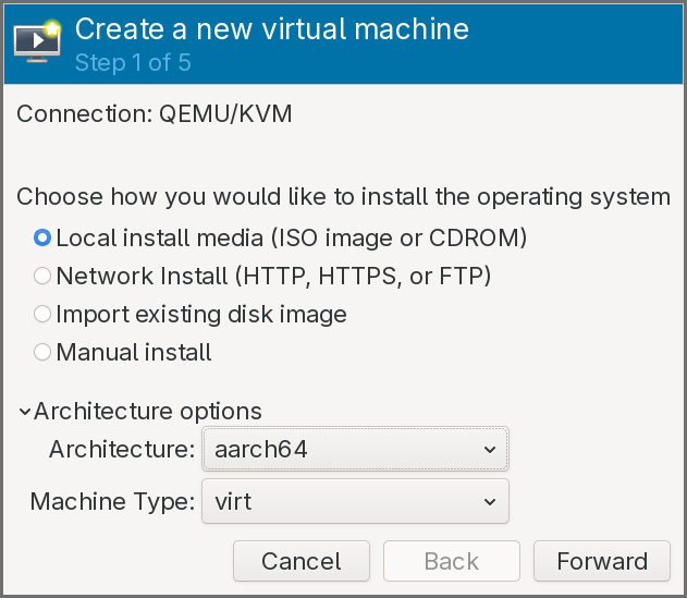
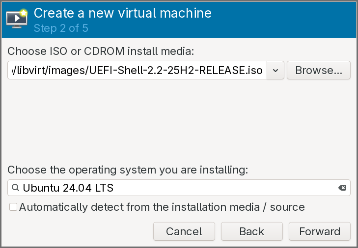
-
The install media should be set the ISO of the UEFI shell previously downloaded, and the operating system can be set as a recent Ubuntu version.
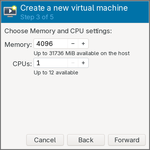
-
Keep the default amount of RAM, but set the CPUs number to
1.
- Keep the default configuration for the storage.
- Click on Customize configuration before install.
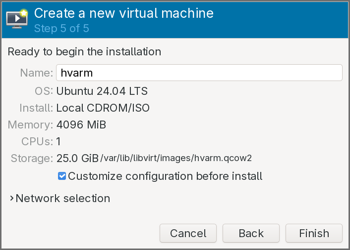
The virtual machine configuration window pops up:
-
In the Overview pane, select the UEFI firmware entry that includes a file path.
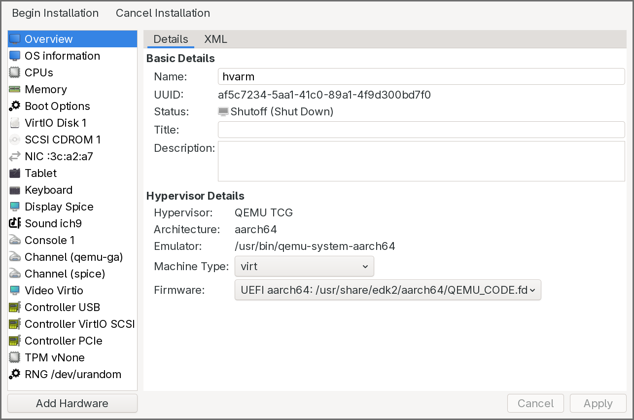
-
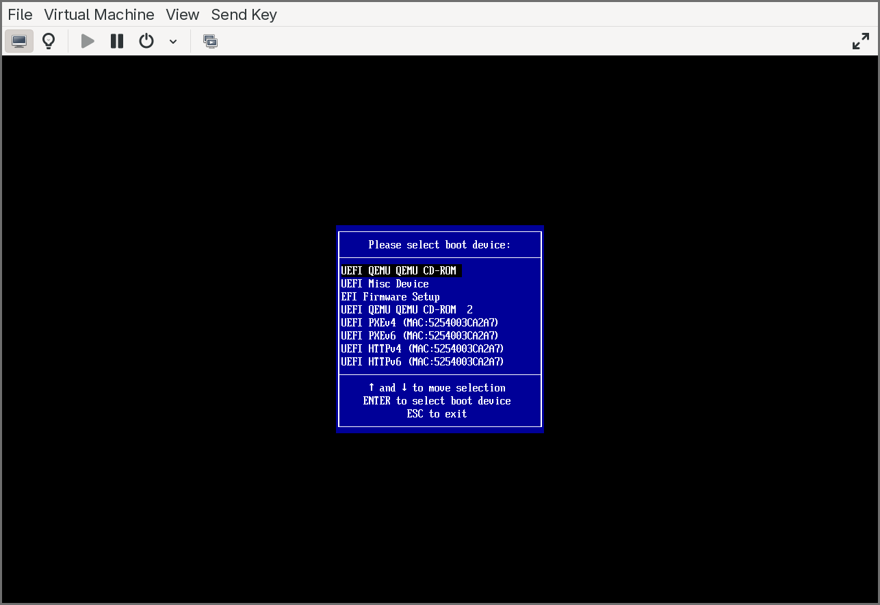
In the Boot Options pane, click on the CDROM to enable it and move it up so that it is the first entry.
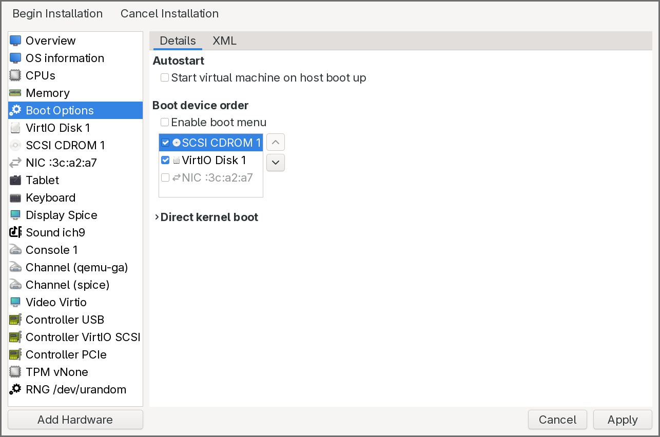
-
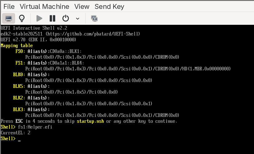
Click on Begin Installation. After a few seconds, the UEFI shell is executed.
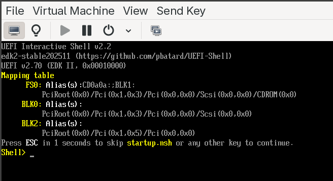
As shown in the above image, the shell also displays a device mapping table on startup, showing the available file systems and block devices. To verify everything is working:
- Type
map -rto refresh and list all available devices and file system mappings. - Type
fs0:to switch to the first available file system (typically the CDROM or ESP). - Type
lsto list files on that file system.
If you see the shell prompt and can navigate file systems, the environment is ready. The VM can be shut down at this point — we will use it in the next section to run our own UEFI application.
EDK II Build System: DSC, DEC, and INF
EDK2 (the EFI Development Kit II) is the open-source reference implementation of the UEFI specification, and it is the build system we will use throughout this series. Before writing any code, it is important to understand how EDK2 organizes and builds firmware components, because the build system is unlike anything in the typical C/C++ world — there are no Makefiles or CMakeLists that you write by hand. Instead, EDK2 uses three declarative metadata file formats that describe your code, your package, and your platform. The build tool (build) reads these files, resolves dependencies, generates intermediate Makefiles, and compiles everything.
The three file formats are:
- INF (Module Information) — describes a single buildable module (a UEFI application, driver, or library).
- DEC (Package Declaration) — describes a package, which is a collection of related modules, header files, library classes, GUIDs, and protocol definitions.
- DSC (Platform Description) — describes a platform build, tying together packages, modules, and configuration into a complete firmware image or a set of buildable targets.
The relationship flows upward: INF files describe individual modules, DEC files group them into packages and declare shared interfaces, and a DSC file pulls everything together into a build. Let’s look at each in detail.
INF — Module Information File
An INF file is the fundamental unit of the EDK2 build system. Every UEFI application, every DXE driver, every PEI module, and every library in EDK2 has exactly one INF file. It tells the build system what the module is, what source files it contains, what it depends on, and how to build it.
An INF file is organized into sections, each introduced by a bracketed header. The most important sections are:
[Defines] — metadata about the module. This includes the module’s name, its GUID (every EDK2 module has a unique GUID), the module type (which determines the entry point signature, linking model, and how the binary is packaged), and the entry point function name. The module type is critical: UEFI_APPLICATION produces a standalone UEFI application (like the one we will write), DXE_DRIVER produces a DXE-phase driver, PEIM produces a PEI module, and BASE or DXE_RUNTIME_DRIVER cover other categories. The entry point name tells the build system which C function to call when the module is loaded — for a UEFI application, this is typically a function that receives the image handle and the system table pointer.
[Sources] — the list of source files (C, assembly, etc.) that make up the module. Paths are relative to the INF file’s location. Architecture-specific sources can be specified with architecture filters like [Sources.AARCH64] or [Sources.X64], so the same module can include different assembly files for different targets.
[Packages] — a list of DEC files (by path) that the module depends on. This tells the build system where to find the header files, library class declarations, GUIDs, and protocol definitions that the module’s source code references. Almost every module depends on at least MdePkg/MdePkg.dec, which is the core UEFI specification package containing the fundamental type definitions, protocol headers, and library class interfaces.
[LibraryClasses] — the library classes (not specific library instances) that the module requires. EDK2 uses an indirection model for libraries: a module declares that it needs a library class (for example, UefiLib, DebugLib, MemoryAllocationLib), and the DSC file decides which concrete library instance satisfies that class for a given platform and module type. This allows the same module to be built with different library implementations on different platforms without changing the module’s INF.
[Protocols], [Guids], [Ppis] — these sections declare which UEFI protocols, GUIDs, or PEI PPIs the module consumes or produces. The build system uses these to resolve the GUID values from the DEC files listed in [Packages] and to generate dependency expressions for driver dispatch ordering.
A minimal INF for a UEFI application might look like this:
[Defines]
  INF_VERSION       = 1.25
  BASE_NAME         = HelloWorld
  FILE_GUID         = a912f198-7f0e-4803-b908-b757b806ec83
  MODULE_TYPE       = UEFI_APPLICATION
  VERSION_STRING    = 1.0
  ENTRY_POINT       = UefiMain

[Sources]
  HelloWorld.c

[Packages]
  MdePkg/MdePkg.dec

[LibraryClasses]
  UefiApplicationEntryPoint
  UefiLib
This tells the build system: compile HelloWorld.c as a UEFI application, resolve headers and definitions from MdePkg, link against implementations of UefiApplicationEntryPoint and UefiLib (whichever instances the DSC selects), and call UefiMain as the entry point.
DEC — Package Declaration File
A DEC file defines a package — a logical grouping of related modules, headers, library classes, and interface definitions. If you think of an INF as describing a single brick, the DEC describes the mold catalog: it declares what library classes, GUIDs, protocols, and PPIs are available in this package for other packages and modules to reference.
Packages in EDK2 serve a similar role to shared libraries or header-only packages in traditional development: they define interfaces without mandating a single implementation. The key DEC sections are:
[Defines] — the package name, GUID, and version. The package GUID uniquely identifies the package in the EDK2 ecosystem.
[Includes] — lists the directories (relative to the DEC file) that contain public header files. When a module’s INF lists this DEC in its [Packages] section, these include directories are added to the compiler’s include path. This is how modules find protocol headers, type definitions, and library class interfaces.
[LibraryClasses] — declares the library classes that this package defines. Each entry maps a library class name to its public header file. For example, MdePkg.dec declares UefiLib and points to its header — any module can then list UefiLib in its [LibraryClasses] section, and the build system knows which header to use. The concrete implementation is chosen later in the DSC.
[Guids], [Protocols], [Ppis] — these sections declare the GUID values for all GUIDs, UEFI protocols, and PEI PPIs defined by the package. Each entry maps a C-language name (used in source code) to its actual GUID value. For example, MdePkg.dec declares gEfiSimpleTextOutProtocolGuid with its corresponding 128-bit GUID. When a module includes the protocol header and references this name, the build system resolves it to the GUID value declared here.
[PcdsFixedAtBuild], [PcdsPatchableInModule], [PcdsDynamic] — Platform Configuration Database (PCD) declarations. PCDs are EDK2’s mechanism for build-time and runtime configuration values — they are essentially typed, named constants (or variables, depending on the PCD type) that modules can query. A DEC declares the available PCDs with their types and default values; the DSC can override those defaults for a specific platform. Common examples include debug message levels, default serial port baud rates, and memory region base addresses.
The core EDK2 packages that most projects reference are:
- MdePkg — the UEFI and PI specification type definitions, protocol headers, and base library class declarations. Nearly everything depends on this.
- MdeModulePkg — reference implementations of standard UEFI modules (DXE core, BDS, variable drivers, etc.) and their associated library classes.
- ArmPkg — ARM architecture-specific library classes, drivers, and helper code (exception handling, cache maintenance, MMU configuration).
- ArmVirtPkg — the platform package for ARM virtual machines (QEMU
virt), which provides the DSC and flash description files that tie everything together for our target platform.
DSC — Platform Description File
A DSC file is the top-level build description. It defines what to build, how to build it, and which library instances to use. When you invoke the EDK2 build command, you point it at a DSC file, and it produces a complete set of firmware binaries (or, in our case, a standalone UEFI application).
The DSC is where all the pieces come together. The key sections are:
[Defines] — platform metadata and build configuration. This includes the platform name, GUID, the DSC specification version, the output directory, the target architecture (AARCH64 in our case), and the build target type (DEBUG or RELEASE). It also specifies the BUILD_TARGETS and SKUID_IDENTIFIER for multi-SKU builds.
[LibraryClasses] — this is the most important section in the DSC and the one that newcomers find most confusing. It maps every library class to a concrete library instance (an INF file). This is where EDK2’s indirection model comes together: when a module’s INF says it needs DebugLib, the DSC decides which DebugLib implementation to link — it could be DebugLib backed by a serial port, a memory buffer, or a null implementation that discards all output. The mapping can be global (applies to all modules) or filtered by module type using syntax like [LibraryClasses.common.UEFI_APPLICATION], so UEFI applications can use a different library instance from DXE drivers.
[Components] — the list of modules (INF files) to build. Each entry is a path to an INF. Optionally, per-module library class overrides can be specified inline, allowing a single module to use a different library instance from the global default.
[PcdsFixedAtBuild], [PcdsPatchableInModule], etc. — platform-specific PCD overrides. These sections let the DSC set configuration values that differ from the defaults declared in the DEC files. For example, a DSC for a debug build might set the debug print level PCD to verbose, while a release build sets it to errors-only.
[BuildOptions] — compiler and linker flag overrides. This is where you can add architecture-specific compiler flags, optimization levels, or warning settings. For cross-compilation targeting AArch64, this is where the build system picks up the correct GCC prefix.
A simplified DSC for building a single UEFI application for AArch64 might look like this:
[Defines]
  PLATFORM_NAME           = HvArmPkg
  PLATFORM_GUID           = d1f2e3a4-5b6c-7d8e-9f00-a1b2c3d4e5f6
  PLATFORM_VERSION        = 0.1
  DSC_SPECIFICATION       = 1.28
  SUPPORTED_ARCHITECTURES = AARCH64
  BUILD_TARGETS           = DEBUG|RELEASE

[LibraryClasses]
  UefiApplicationEntryPoint|MdePkg/Library/UefiApplicationEntryPoint/UefiApplicationEntryPoint.inf
  UefiLib|MdePkg/Library/UefiLib/UefiLib.inf
  BaseLib|MdePkg/Library/BaseLib/BaseLib.inf
  BaseMemoryLib|MdePkg/Library/BaseMemoryLib/BaseMemoryLib.inf
  DebugLib|MdePkg/Library/UefiDebugLibConOut/UefiDebugLibConOut.inf
  PrintLib|MdePkg/Library/BasePrintLib/BasePrintLib.inf
  # ... additional library class mappings ...

[Components]
  HvArmPkg/Application/HelloWorld/HelloWorld.inf
The | separator in [LibraryClasses] maps a class name (left) to its implementing INF (right). The [Components] section says “build this one module.” The build tool will read the module’s INF, resolve its library class dependencies against the DSC’s mappings, find the required headers via the DEC files, and compile and link everything into a PE/COFF UEFI application.
How the three files work together
The build flow ties all three together:
- You invoke
build -p HvArmPkg/HvArmPkg.dsc -a AARCH64 -t DEBUG. - The build tool reads the DSC. It finds the module to build (
HelloWorld.inf) in[Components]. - It reads the module’s INF. The INF says it needs
MdePkg/MdePkg.decand library classesUefiApplicationEntryPointandUefiLib. - It reads
MdePkg.decto find include directories and resolve any GUIDs, protocols, or PCDs the module references. - It consults the DSC’s
[LibraryClasses]section to find which INF implementsUefiApplicationEntryPointandUefiLib. It then recursively resolves those libraries’ own dependencies the same way. - Once the full dependency graph is resolved, it generates Makefiles, compiles all source files with the AArch64 cross-compiler, and links the final PE/COFF binary.
- The output is a
.efifile in the build output directory, ready to be placed on a FAT32 file system and loaded by the UEFI firmware.
This indirection model — modules declare what they need, the platform decides how to satisfy it — is what makes EDK2 highly portable. The same module INF can be built for x86, AArch64, or RISC-V by simply using a different DSC with appropriate library class mappings. It is also what makes EDK2 intimidating at first: the separation between declaration and implementation means you cannot understand a build by reading any single file.
Building a First UEFI Application
With the build system understood and the environment ready, we can now compile and run a real UEFI application on our AArch64 virtual machine. The application is deliberately simple — it reads the current exception level from the CurrentEL system register and prints it. This will let us verify not only that the build pipeline works, but also whether the virtual machine is configured to give us access to EL2, which is a prerequisite for the hypervisor we will build in later chapters.
One thing to keep in mind: UEFI applications do not have access to a standard C library. There is no stdio.h, no stdlib.h, no printf in the traditional sense. Instead, all functionality comes from EDK2’s own library classes — UefiLib provides Print() for console output (which uses the UEFI console protocol internally), BaseLib provides basic utility functions, and BaseMemoryLib covers memory operations. You write C code, but everything underneath is wired through EDK2’s library abstraction rather than libc.
Cloning the repository
The project repository includes EDK2 as Git submodules, so it must be cloned recursively:
git clone --recursive https://gitlab.com/0xabe.io/hvarm.git/
This will take a while — EDK2 is a large repository with a long history. Once cloned, the project structure contains our hypervisor package (HvArmPkg) alongside the full EDK2 source tree.
The Helper application
The application we will build is a small helper that reads the processor’s current exception level. It is located at HvArmPkg/Applications/Helper/Helper.c. The code reads the CurrentEL system register using an ARM intrinsic and prints the result. On a standard QEMU virt machine without virtualization extensions exposed, the firmware hands off at EL1 and the application will report EL1. Later, once we enable virtualization in QEMU, the same application will report EL2 — confirming that the firmware is running at the hypervisor exception level and that our future hypervisor code will have the privilege it needs.
Building with the build script
The repository includes a build.py script that wraps the EDK2 build process and handles the boilerplate. The first time you run it, it will build EDK2’s BaseTools (the C utilities that the build system itself relies on — the build tool, GenFv, GenFw, etc.). This is a one-time step and takes a minute or two. Subsequent builds only compile the application itself and complete in a few seconds.
The script can also package the compiled .efi binary into a ISO image, which makes it easy to attach to the virtual machine as a CDROM. Before running it, verify that the AArch64 cross-compiler prefix in the script matches what is installed on your system. Look for the line that sets GCC_AARCH64_PREFIX — on most Debian and Arch installations, the correct value is aarch64-linux-gnu-, but it may differ on other distributions.
To build the application and generate an ISO:
./build.py --iso /tmp/hvarm.iso
The end of the build output should look like this:
- Done -
Build end time: 20:40:16, Mar.01 2026
Build total time: 00:00:04

INFO: Generating ISO at /tmp/hvarm.iso...
INFO: ISO generation complete.
The *.pdb copy error that appears in the build output is harmless — PDB debug symbol files are only generated on Windows builds, and the makefile ignores the failure.
Running the application
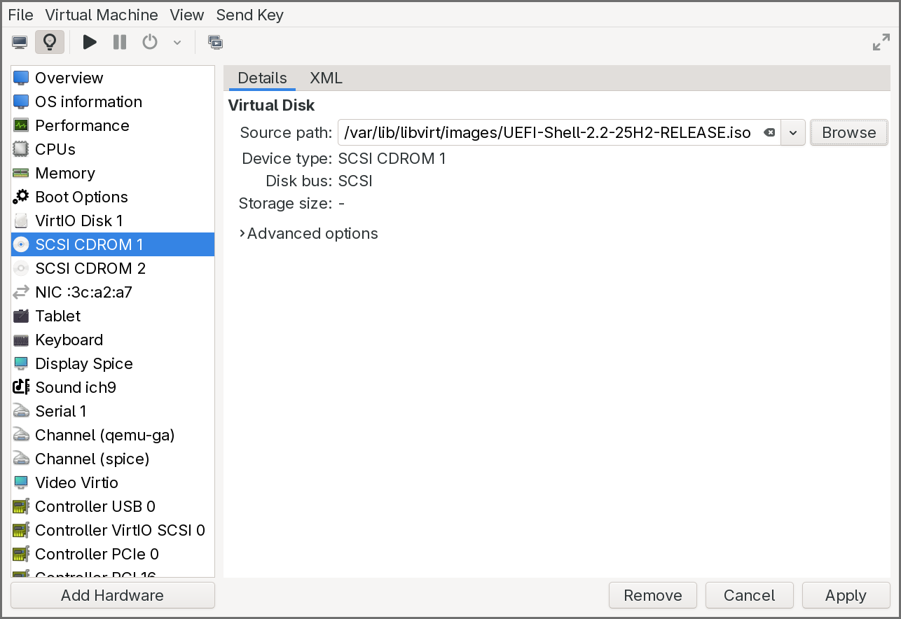
To run the application on our virtual machine, we need to attach the generated ISO as a second CDROM while keeping the UEFI Shell ISO on the first CDROM.
In virt-manager:
- Open the virtual machine’s configuration.
-
Add a new Storage device of type CDROM and select
/tmp/hvarm.iso.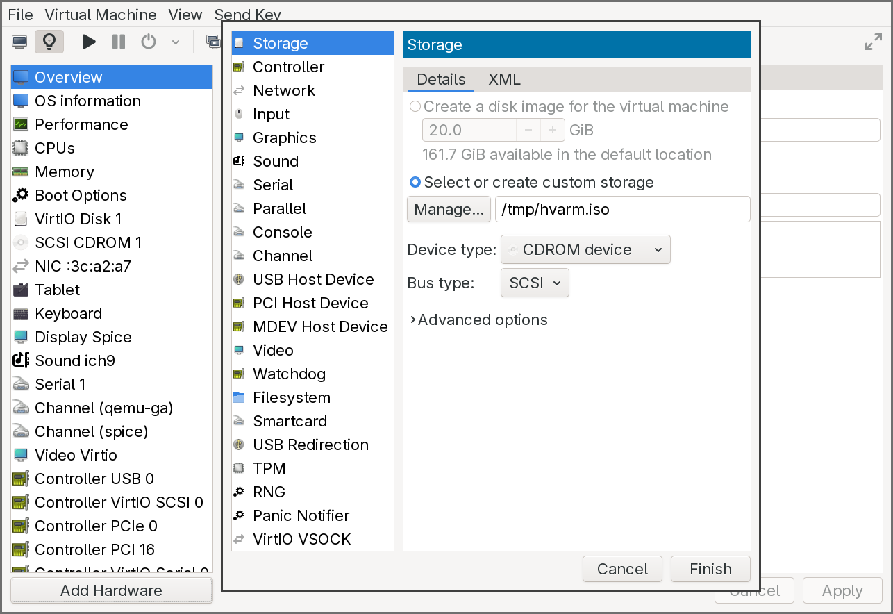
-
Ensure the first CDROM still has the UEFI Shell ISO attached and is set as the first boot device in the Boot Options pane.
- Start the virtual machine.
The firmware will boot into the UEFI Shell from the first CDROM. The shell’s startup device mapping table should show two file system entries: fs0: for the UEFI Shell CDROM and fs1: for the application CDROM. If fs1 does not appear in the mapping table, type exit at the shell prompt to return to the UEFI boot menu, then select the CDROM entry — this forces the firmware to connect the device and make it visible.
Once both file systems are mapped, switch to the application file system and run the helper:
Shell> fs1:
FS1:\> Helper.efi
Or simply:
Shell> fs1:Helper.efi
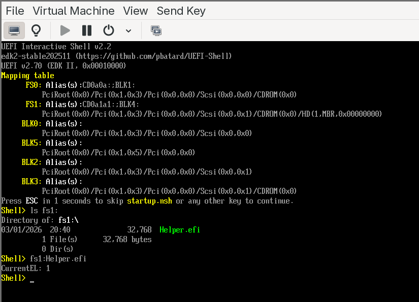
The application will print the current exception level. At this point, it will report EL1 — the standard exception level for UEFI applications on QEMU’s virt machine when virtualization extensions are not exposed to the guest firmware.
Enabling EL2: exposing virtualization in QEMU
To build a hypervisor, we need the firmware (and our application) to run at EL2. We need to add virtualization=on to QEMU’s -machine argument. Since we are using libvirt, this requires a small XML configuration change.
First, with the VM running, retrieve the current QEMU machine argument from a terminal:
pgrep -a qemu-system-a
Look for the -machine argument in the output. It will look something like:
virt-10.2,usb=off,gic-version=2,dump-guest-core=off,memory-backend=mach-virt.ram,pflash0=libvirt-pflash0-format,pflash1=libvirt-pflash1-storage,acpi=on
Save this value — you will need it in the next step. Then shut down the VM.
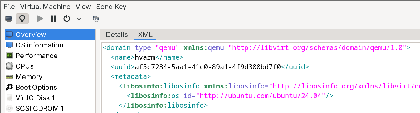
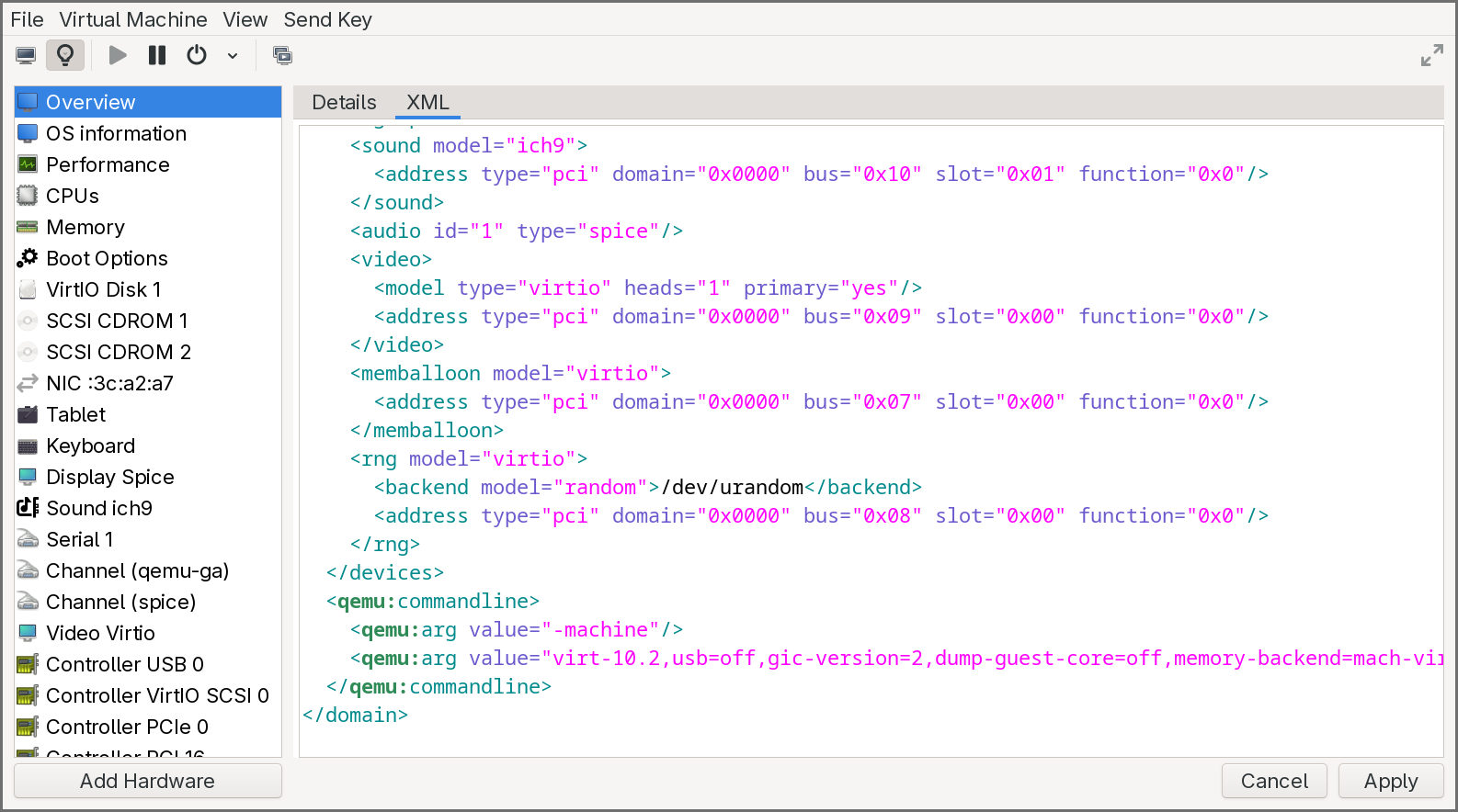
Now edit the VM’s XML definition to inject a custom QEMU command-line argument. This can be done from a terminal with virsh edit <VM_NAME> or from the XML editor in virt-manager. Two changes are needed:
First, at the beginning of the XML, modify the <domain> tag to add the QEMU command-line namespace:
<domain xmlns:qemu="http://libvirt.org/schemas/domain/qemu/1.0" type="qemu">
Second, at the end of the XML, just before the closing </domain> tag, add a <qemu:commandline> block that overrides the machine argument with virtualization enabled. Take the machine value you saved earlier and append ,virtualization=on:
<qemu:commandline>
  <qemu:arg value="-machine"/>
  <qemu:arg value="virt-10.2,usb=off,gic-version=2,dump-guest-core=off,memory-backend=mach-virt.ram,pflash0=libvirt-pflash0-format,pflash1=libvirt-pflash1-storage,acpi=on,virtualization=on"/>
</qemu:commandline>
Save the XML and start the VM again. Boot into the UEFI Shell, and run Helper.efi once more. This time, the application should report EL2 — the hypervisor exception level. The firmware is now running with full access to the virtualization hardware, and our UEFI application inherits that privilege.
This confirms that the development environment is fully operational: we can build AArch64 UEFI applications, run them on an emulated ARM platform, and execute at EL2. In the next chapter, we will start writing the actual hypervisor — claiming EL2, building Stage 2 page tables, and deprivileging the boot environment to EL1.
Conclusion
This article covered a lot of ground to lay the foundation for the rest of the series.
We started with hardware virtualization, comparing how x86 and ARM approach the problem. On x86, Intel’s VT-x retrofits virtualization onto an architecture that was never designed for it — splitting execution into VMX root and non-root modes, managing guest state through the opaque VMCS, and controlling trapping via bitmap-based execution controls. On ARM, the exception level hierarchy (EL0–EL3) integrates virtualization natively: the hypervisor lives at EL2 with its own registers and translation regime, context switching is done explicitly in software, and trapping is configured through HCR_EL2 and its companion registers. We also covered the two interrupt virtualization approaches — x86’s APIC interception versus ARM’s GIC virtual CPU interface — and walked through the hypervisor lifecycle on both architectures.
We then examined the distinction between Type 1 and Type 2 hypervisors, exploring what each must build (or can borrow from a host kernel), and how the Virtualization Host Extensions on ARMv8.1-A eliminated the legacy EL2 stub that KVM previously required. From there, we defined our target: a passthrough hypervisor that identity-maps all physical memory and devices through Stage 2 translation, runs a single guest transparently, and traps only the operations we choose to observe.
The UEFI deep dive walked through all seven boot phases — from the SEC phase’s cache-as-RAM initialization and root-of-trust establishment, through PEI’s memory training, DXE’s driver dispatch and security isolation setup, BDS’s boot policy and Secure Boot verification, and TSL where our hypervisor will eventually live as a UEFI application. We covered how each phase differs between x86 and ARM, and how the UEFI Shell fits into the picture as a development and debugging tool.
With the conceptual foundation in place, we set up the practical environment: an AArch64 cross-compilation toolchain, QEMU with EDK2 firmware, and the UEFI Shell for interactive testing. We walked through the EDK2 build system — INF, DEC, and DSC files — and the indirection model that makes EDK2 portable. Finally, we built and ran our first UEFI application, confirmed that eventually our code runs at EL2. This is the starting point for everything that follows
In the next chapters, we will begin implementing the hypervisor itself. The first step is to claim EL2 permanently: set up an exception vector table, configure HCR_EL2 and SCTLR_EL2, and build identity-mapped Stage 2 page tables that cover the entire physical address space. We will then deprivilege the UEFI environment to EL1, verify that the system continues to function as a guest, and handle our first trap — proving that we have a working hypervisor sitting invisibly beneath the firmware.